Dead Battery Music (dBm) Circuits
making sounds & music with digital logic gates.
- The Art of Power Starving
- dBm festival docs 2025, 2026
- chaosz
- McMOS handbook 1973 - the bible for Lunetta style music electronics
- PhishNoise
The Art of Power Starving
or how to make dead battery music
It has been known since the early days of electronic music that devices such as radios, amplifiers, and musical instruments can produce unusual sound artifacts during power-up and power-down. Likewise, battery-powered devices often change their sound—or even behave completely differently—when the battery runs low.
A simple digital square-wave oscillator typically produces a dull, harsh beep. However, when power starving is applied, strange, chaotic noises and self-modulation effects emerge, transforming the sound completely.
In recent decades, this phenomenon has inspired the development of instruments within the experimental electronic music scene that deliberately exploit the effects of “power starving.” A common technique is to insert a variable resistor between the (stable) power supply and a simple CMOS oscillator. This resistor—often called a “dead battery potentiometer”—simulates the increasing internal resistance of a discharging battery. As a result, power starving can be controlled reproducibly, even in mains-powered instruments or devices equipped with fresh batteries.
Experiments have shown that it is useful not only to add such a “dead battery potentiometer,” but also to make the operating voltage adjustable within a musically interesting range. While standard CMOS oscillators are typically powered with 5–18 V DC in digital applications, the “magic range” for power starving is much lower—often between 0.5 and 2.5 V.
In recent years, members of Kulturgüterschuppen have revisited this topic and conducted new experiments. They found that a true adjustable current limiter—also known as a constant current source (CCS)—can further expand the sonic possibilities of power starving. Since CMOS oscillators operating in the magic voltage range typically consume only a few microamperes, an adjustable current limiter from 0 to 50 µA was developed to generate even more chaotic and unstable sounds.
The real fun begins when power starving is not controlled statically by potentiometers, but made voltage-controllable, as in analog modular synthesizers. This allows power-starved sounds to be modulated by any control source, including self-modulation feedback, envelopes, low-frequency oscillators, or combinations thereof. Multiple simple power-starved oscillators can be interconnected in complex, neural-network-like topologies, enabling endless sound experiments.
Power starving is not limited to dedicated oscillators. In fact, it can be applied to virtually any electronic musical instrument—from sound toys and circuit-bent devices to “Lunetta-style” synthesizers. Circuit bending can even be made safer using power starving techniques: reducing the supply voltage and/or limiting the current lowers the risk of damaging an instrument when shorting pins during experimentation. Since Lunetta synthesizers already use CMOS oscillators, applying power starving to them is a natural extension.
dBm festival docs 2025, 2026
20. - 24. May 2026 @ Kulturgüter-Schuppen, Bahnhofstr.16 D-72144 Dusslingen
dbm
1) dBm (deciBel-milliwatts) is a unit of power level expressed using a logarithmic decibel (dB) scale respective to 1 mW.
this is not what we are talking about here :-)
2) acronym for "dead Battery music". dBm occurs when electronic circuits that generate audio signals, not necessarily musical instruments in the narrower sense, have their power supply reduced to such an extent that they generate artifacts or even completely different signals than in normal operation. This process is also known as “power starving”. Oscillator circuits with CMOS logic gates have proven to be particularly suitable.
dBM 2026 is a DIY workshop festival for advanced *) music electronic tinkerers where we will investigate the sonic limits of CMOS logic gate circuits. We want to delve deep into theory and practice and systematically develop, measure and optimize dBm circuits, so that at the end of the workshop the participants can take home a new dBm synth, or at least many ideas.
The workshop will take place near Tübingen, more precisely, 7km away in Dusslingen, right next to the train station in the Kulturgüter-Schuppen. There is an electronics workshop with lots of, mostly free, material, as well as a laser cutter and other tools.
Accomodation will be in the local YMCA house, which is 15min walking distance. We can also use the kitchen there in the evening for self-catering.
Drinks, fruit and something to nibble on will of course also be available during the day in the KulturGüterSchuppen. We plan a public concert on Saturday evening (23.May) at the end of the event, where we will present our “research results”.
The costs for 4 overnight stays will be around 100€ per person. Cost of care depends on how often we want to cook ourselves.
I will be able to give more details when the list of participants is complete.
If you would like to take part, please send a short description of what you do and what you would like to contribute technically and musically.
Register as early as possible by email to kulturgueterschuppenÄTgooglemailDOTcom, as places are limited.
Note: Everything we develop together (schematics, hardware) is subject to the CC NC BY SA license. We develop for the DIY community!
*) : advanced means: you can read a circuit diagram and put it on a breadboard, solder it on a breadboard or assemble a PCB without outside help.
building test hardware (dBm 2025)
our dBm research system consists of these modules :
- Power supply : USB powered, LiPo battery, 5V out
- Power starving controller : voltage and current control with potentiometers & CV inputs
- CMOS oscillator (D.U.T.) : various topologies of Schmitt-Trigger based squarewave oscillators
- High impedance buffer & amplifiers: line and feedback outputs Potentiometers for gain and feedback
- C-multiplier: electronically variable capacitance with potentiometer and CV control. Acts as capacitive load for D.U.T.
- triple CV out pseudo random pattern generator : for controlling CVs of power staving controller and C-multipliers
- vactrol module : DIY dual vactrol with exponential CV control for potentiometer replacement in D.U.T.
overview experimental dBm setup

dBm impressions 2025,2026
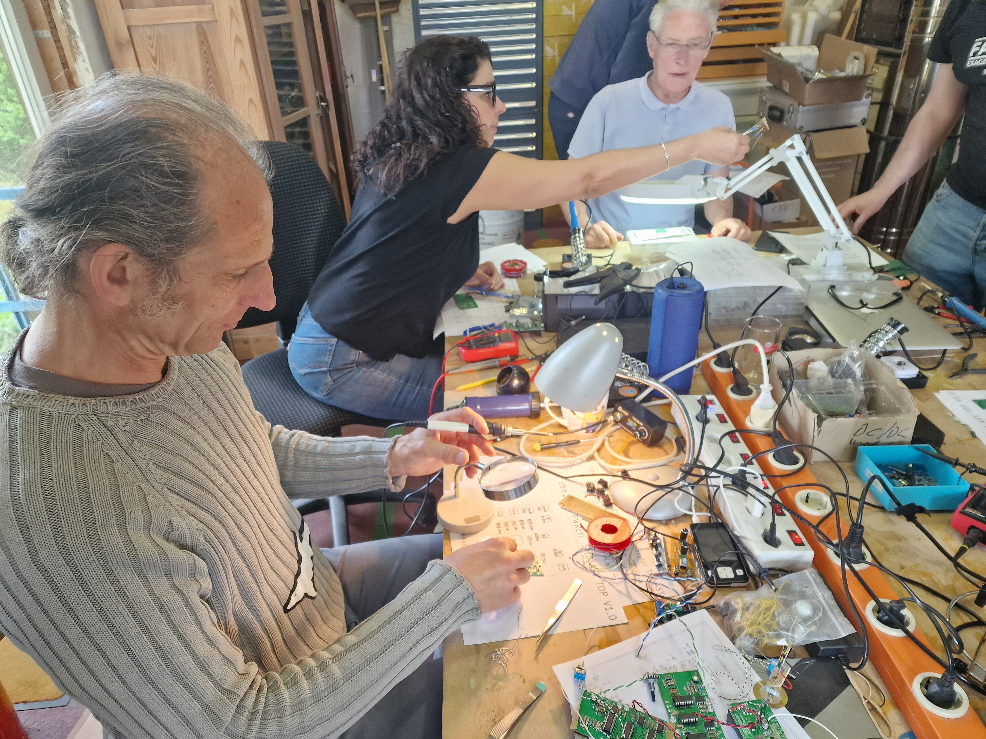 |
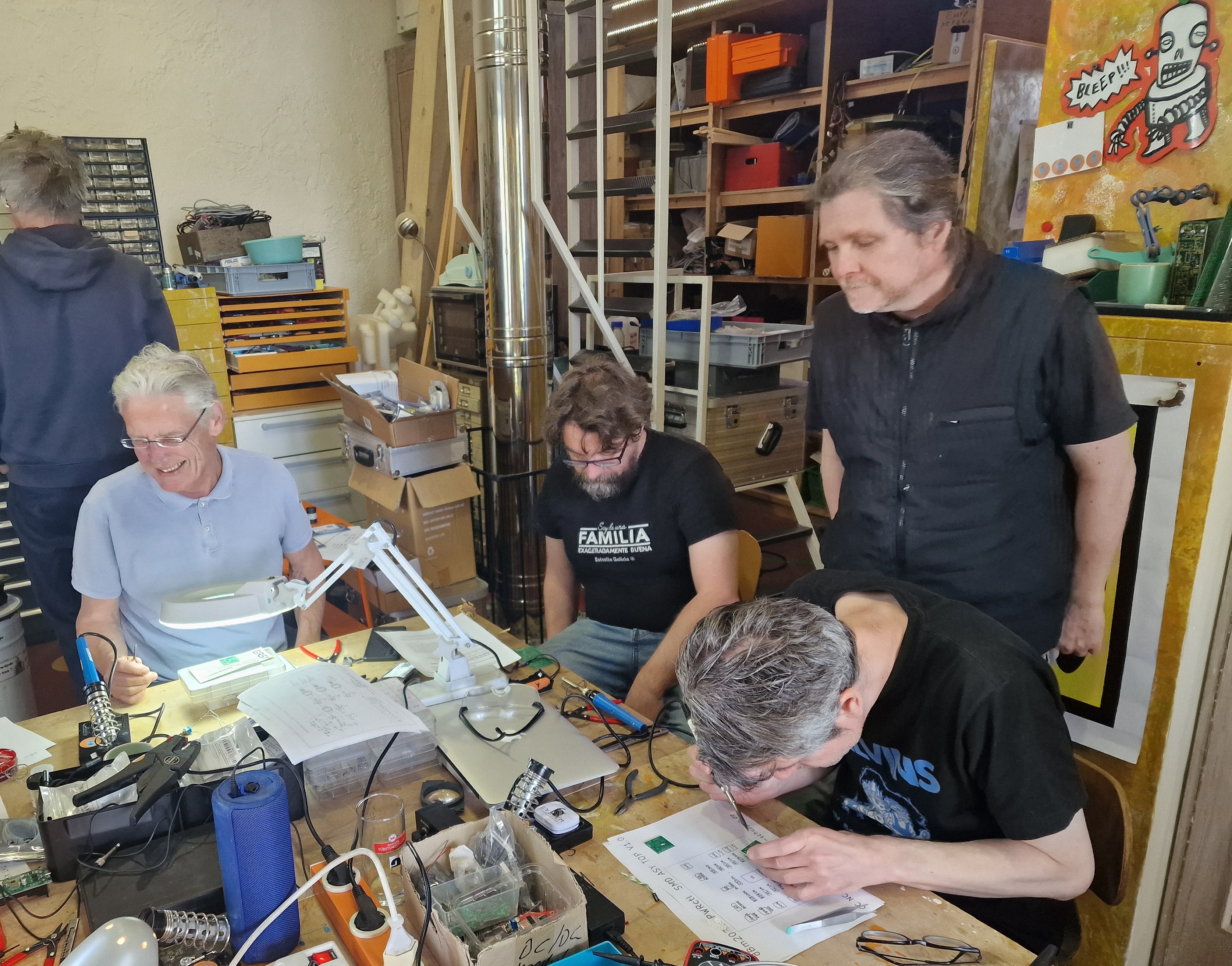 |
 |
chaosz
chaosz is the Kulturgüter-Schuppen classic of dBm instruments. It was created in 2010 at the first Circuit Control Festival Dresden in the legendary Ostpol location. CHAOSZ (CHAOtic OSZillator), is a simple astable CMOS oscillator that can be made chaotic by power starving and variable filtering of the power supply. The sound ranges from a boring square wave to stomping locomotives to clucking chickens...


chaosz schematics Version 2011: touch body contacts (BC) and output clipping to preserve the hearing of the remaining ear ;-)
CHAOSZ FAQ
why this exotic CD4085 chip ?
because I got some hundred of them for free. You can use almost any CMOS gate connected as inverter in this circuit
what's this Bruce Willis "die hard" capacitor ?
it creates a "power starving" envelope after switching off chaosz
McMOS handbook 1973 - the bible for Lunetta style music electronics
After more than 50 years, the original Motorola manual from 1973 is still the most important source for CMOS4000 designs.
It is so important for the music electronics engineer because, in addition to the digital possibilities of the 4000 CMOS logic, it describes the analog applications in great detail. Fortunately, I have owned the original edition to this day. Until today, because I decided to destructively scan the book, which cannot be found as a PDF on the Internet, to allow it to survive digitally, because my original is slowly decaying after decades of use. So you can download it here for private use :-)

PhishNoise
PhisNoise is a compact dual dBm oscillator in a fish can. Although it uses only 1 hex inverter chip, 5 transistors and some passive components, it can create its own universe of strange, chaotic, analog sounds , which would be demanding to copy even with a big modular system. All PhishNoise are different. Even if you use the chips from the same manufacturer they sound different due to tolerances. And there are lots of pin compatible hex inverters from different logic families, with or without Schmitt-Trigger inputs and many brands out there. 2 chips can be stacked - yes, all 14 pins parallel - to create more new sounds. A CD40106 together with a 74AHC04 sounds good - most often ;-)
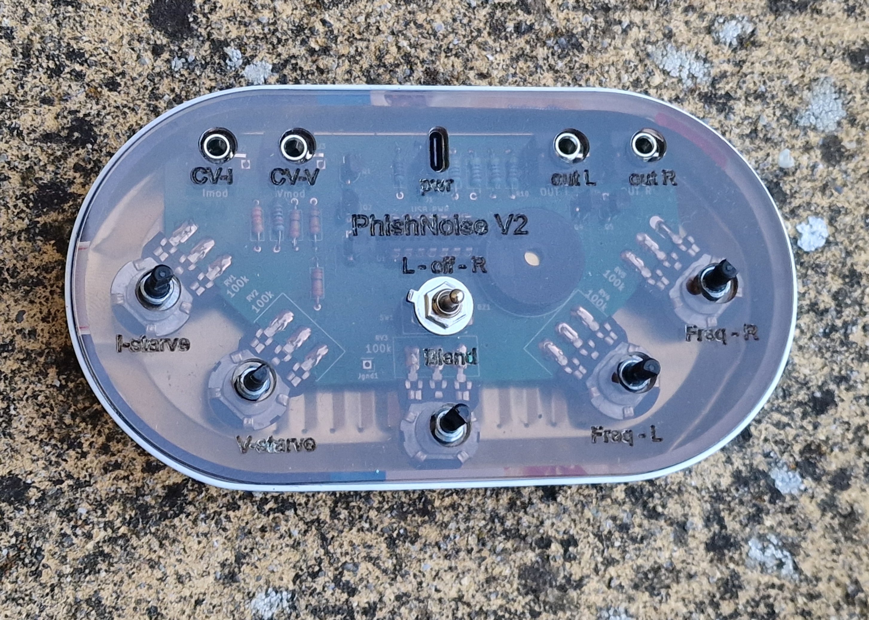
what's inside
2 coupled RC square wave oscillators, each with a tune potentiometer , are supplied by voltage controlled power starving. There are 2 potentiometers to set supply voltage and current limit . Voltage and current also have 3.5mm input jacks for CV. A 5th potentiometer controls an internal capacitive load, which strongly affects the chaotic behavior of the starved oscillators. this load can be switched between the oscillators, with the Left-Off-Right switch. Each oscillator has 3.5mm mono output jack, L-out and L-right.
PhishNoise can be supplied by any USB-C 5V source . If Power banks are used, make sure they don't switch off due to the tiny mA load.
how to play
The nonlinear, chaotic behavior of the circuit makes sounds creation with PhishNoise not really intuitive ;-)
It's all about finding the sweet spots. Turning the same potentiometer will produce different effects depending on the current state of the oscillators. Sometime you turn it from 0 to full and nothing will happen, sometimes a slight touch will shift the sounds to something completely new. It is even possible that turning a potentiometer from A to B, then back to A, the sound will be different because you altered the internal state. PhishNoise has no dedicated BPM knob, because all potentiometers and CV inputs can affect tempo. If you need to play together with others or just need a straight stable beat, you can use the voltage and/or current starving CVs for modulation to get a kind of soft to hard sync.
the bigger picture
PhishNoise can be used as stand alone instrument, but it makes sense to extend it with other devices. Although you can use patch cables to connect the sound outputs straight to the CV inputs, it is obvious that an external feed back loop with a mixer or modular synth will extend the capabilities. A typical setup uses a sound mixer with inputs connected to the 2 PhishNoise audio outs and 2 mixer outs like FX send or Aux out connected to PhishNoise current and voltage starving CV inputs. This feedback loop, together with the mixers sound controls and FX brings PhishNoise closer towards a playable musical instrument. Even more is possible when PhishNoise is integrated as VCO in a modular system, but this can not be discussed here in detail.
There are 2 main use cases for PhishNoise. One is using it as a complex sample generator where the samples later will be processed and used in a DAW. The other is on stage use with a mixer/modular setup described above.
Here are 2 sound examples that use only samples created by PhishNoise in a mixer loop. No other sound sources. The DAW was used to cut and stretch the samples into audio tracks and add some equalizing and reverb :
"ghost riders" by Uwe Schüler
"Himmelsmechanik drkmbnt remix" by Wolfgang Dorninger
building PhishNoise
PhishNoise is available as a DIY kit and there will be workshops where you can build one.
PCB Assembly
it is strongly recommended to follow the assembly instructions step by step otherwise you can ruin your PCB !
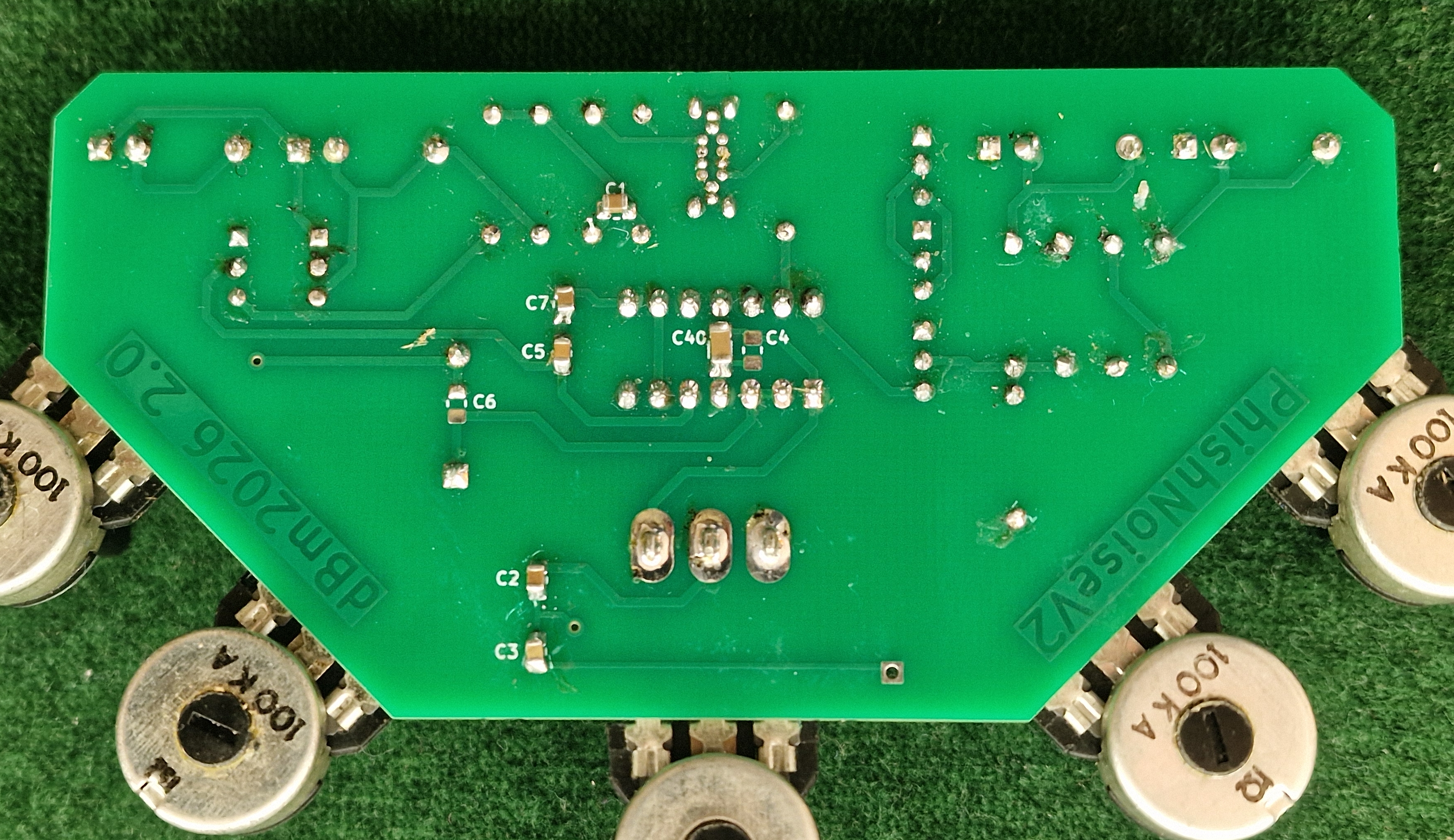
1) SMD assembly
all capacitors are SMD types and located on the solder side. For some workshops the PCBs come with capacitors soldered in place already. Then you can proceed with the next step. If not, no worries, there a only 5 beginner friendly big sized (0805, 1210) capacitors to solder. The 1uF has 2 options : as C4 in 0805, or as C40 in 1210 size. C6 is optional, a matter of (sound) taste :-)
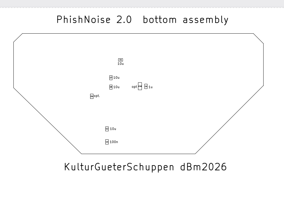
- set 1 solder dot for each capacitor
- take the capacitor with the SMD tweezers in one hand, move it to the pads, and solder it with the solder iron in the other hand to the existing solder dot
- change tweezers against solder tin and solder the other sidevof the capacitor
- repeat this for all SMD components and check the the solder joints before you go to2)
2) THT assembly
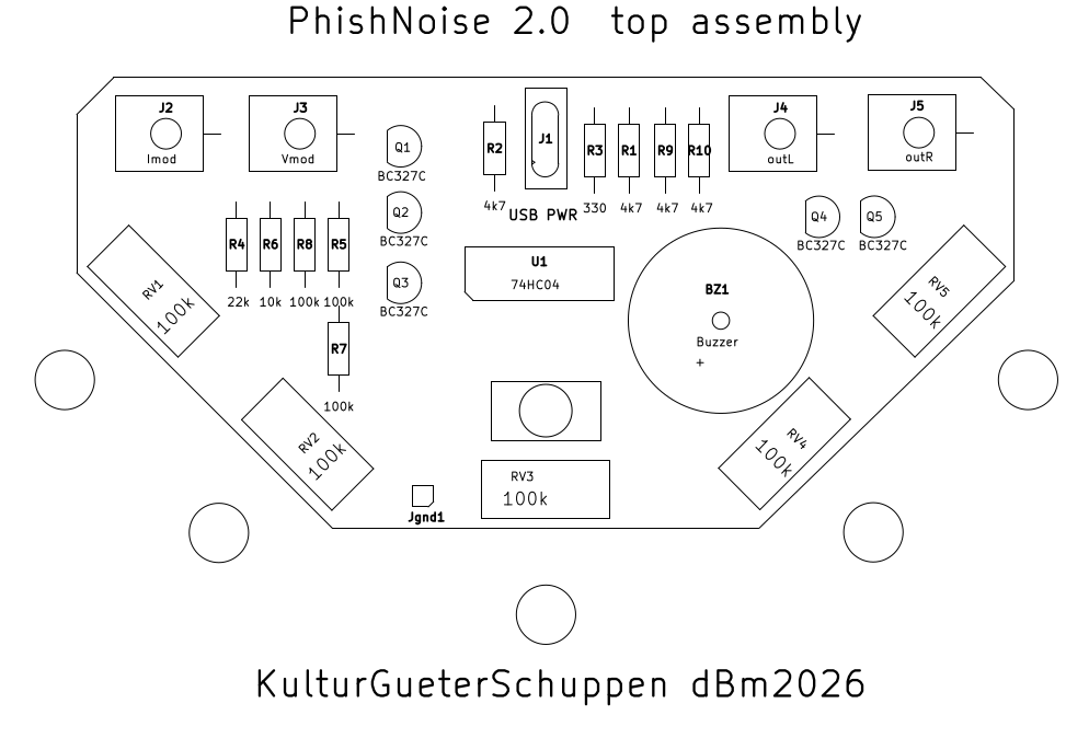
- solder the components in a flat to high order. Populate resistors first. Check color codes before soldering
- next is the chip socket with the chip. Check the direction and that all 14 pins of the chip are in the socket and all socket pins show up on the solder side before soldering !
- then solder the piezo buzzer. There should be no gap between PCB and buzzer
- insert all 5 transistors. Keep the height equal or below the height of the buzzer, otherwise the front panel will not fit
- now the 4 jacks. They must touch the PCB too, so they will have the same height (9mm) as the buzzer
- now the 5 potentiometers, solder 1 pin first for each potentiometer, then check if they all fit the front panel. If so, solder the other pins. Take your time, soldering the potentiometer pads needs lots of heat
- next is the switch. Check that it sits straight and without vertical gap (same height as buzzer/jacks) before soldering it
- finally the USB-C connector. Before inserting it, check that all pins are straight and not bend or broken. Push connector on PCB until base touches the PCB. Double check that all pins are visible on the solder side before soldering the first
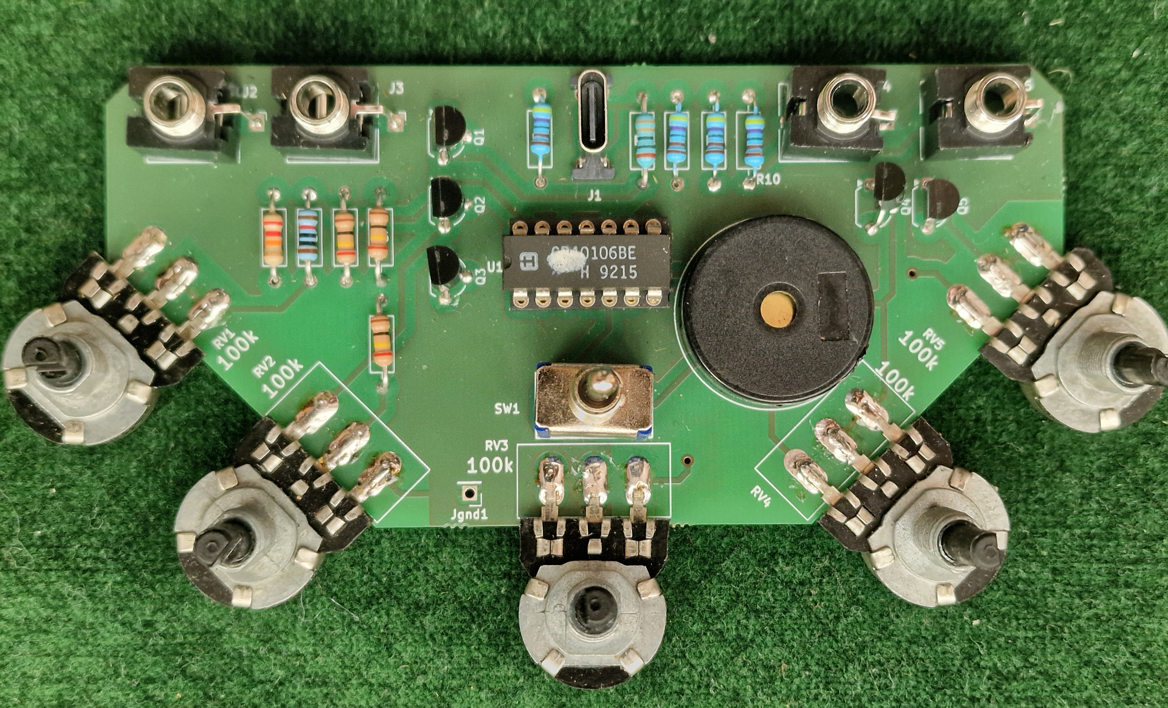
3) Test and final assembly
now it is time to make a functional test. Connect PhishNoise to a USB power supply and the output jacks with audio cables to a sound system and enjoy first noise :-)
If you want to select worlds best sounding hex inverter, do it right now. An additional socket is recommended if you want to compare more than 3 chips to avoid damaging the soldered socket. A ZIF socket would be perfect.
Then the front panel can be mounted. Remove all screws from potentiometers,switch and jacks. Position the front panel. Check that it must sit on all 4 jacks, the switch and the buzzer. then you can fix it by tightening the nuts for jacks and switch. Potentiometer nuts are optional; don't use force because there is no distance spacer and the potentiometers would bend. Instead fix the potentiometer nuts with a small drop of super glue.
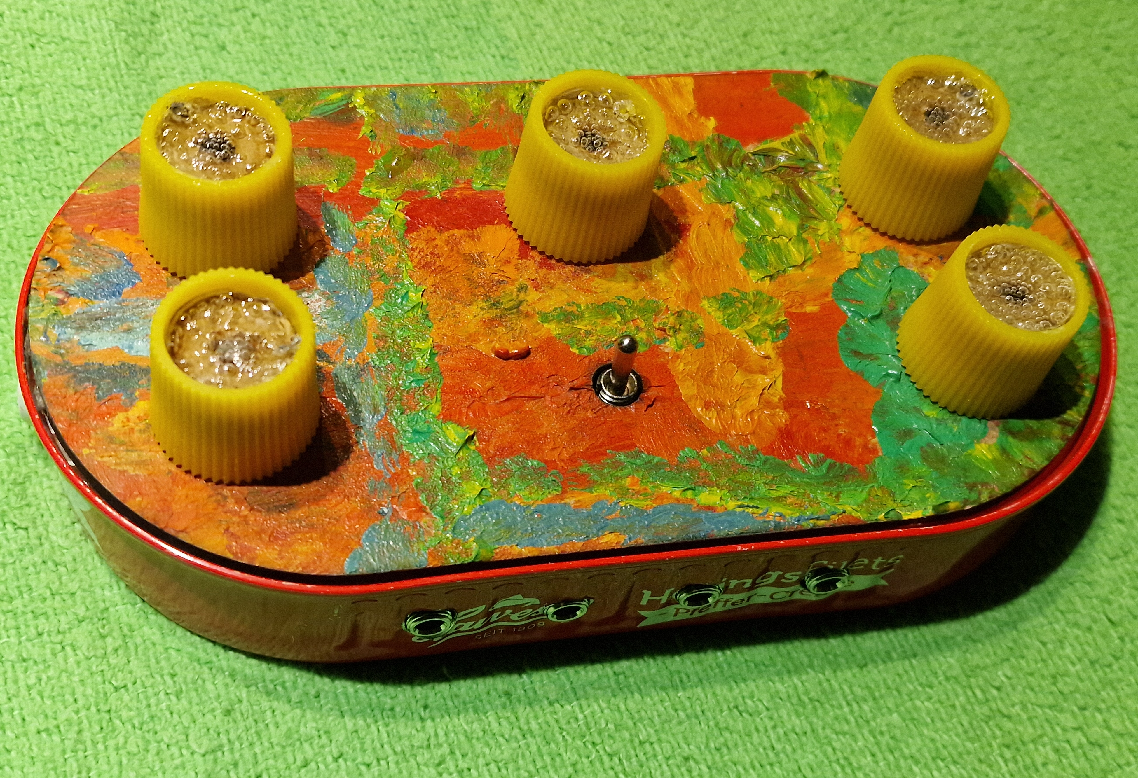
Buy a matching fish can. Eat the fish, bon appetit ! clean the fish can and insert PhisNoise module.
Glue the front panel into the fish can only after you have checked all functions. Have fun playing it !
downloads :
PhishNoise SMD assembly [.pdf]
PhishNoise THT assembly [.pdf]
 |
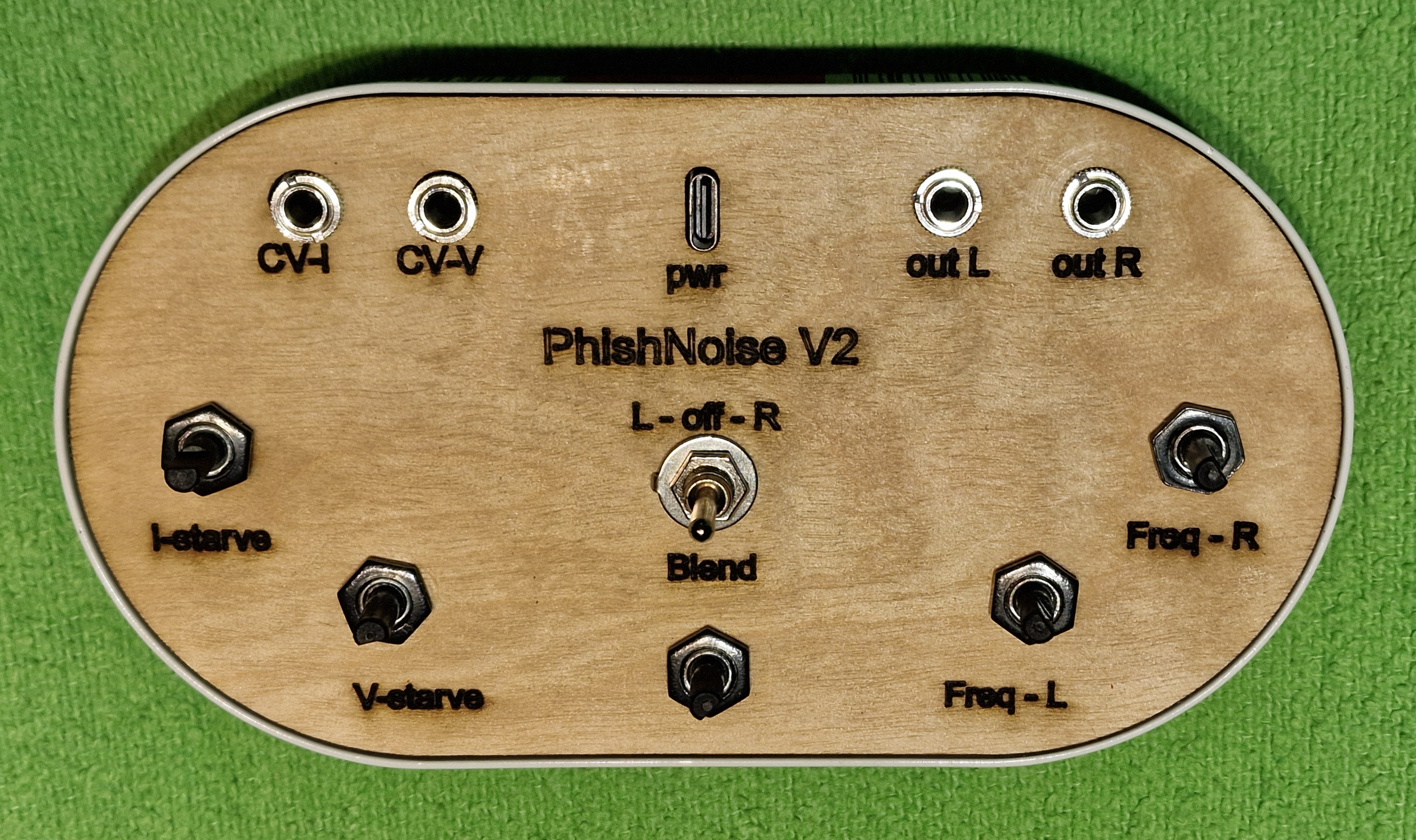 |
| PhishNoise V1 2025 | PhishNoise V2 2026 |