
CMOS-555 Theremin
My friend Wolfgang Dorninger asked me for a recommendation for student workshop suitable DIY Theremin kit. He sent me 4 links and asked me to choose the best design. After watching Youtube vides and listening to sound examples, I compained that all of them were either crap or too expensive and decided to design my own Theremin for him with these specs :
- old school analog design
- about 10€ for PCB + components to be affordable for kids
- low part count for beginner friendly assembly during a 1h workshop
- standard components still in production, no programmable or obsolete parts
- simple standard coils for oscillators
- tunable by potentiometer
- no variable capacitors or other trimmable parts
- simple to play with pitch only antenna and
- playable antenna distance range of > 50cm
Well, I underestimated the effort to realize this "small" project. It took me 6 prototypes until I was satisfied with the result. Here it is :
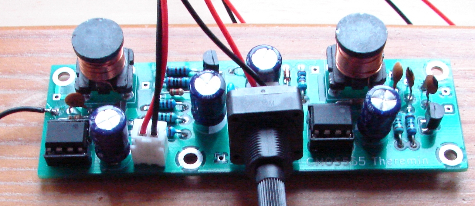
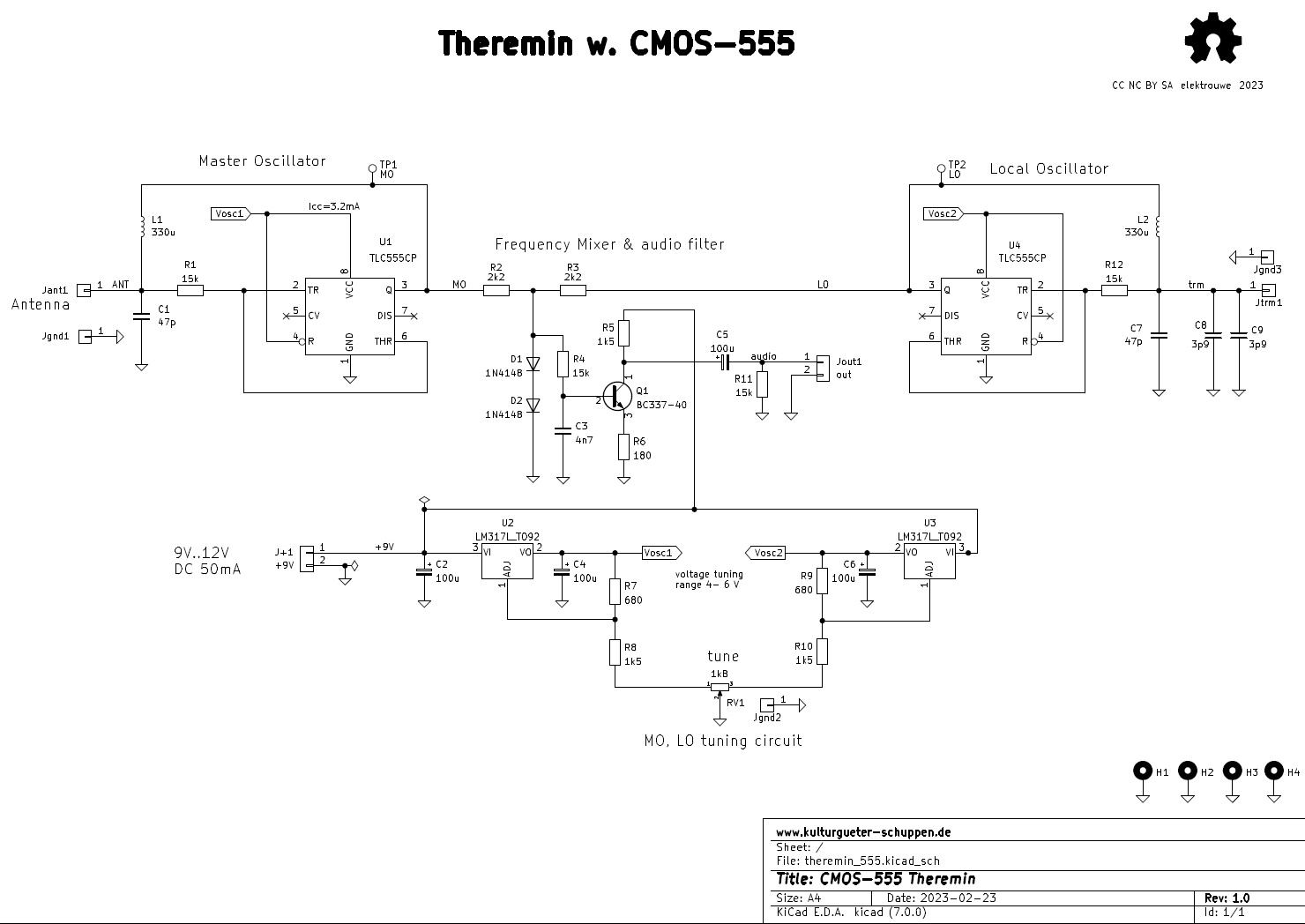
circuit description :
Master and Local Oscillator are Schmitt-Trigger LC-oscillators. My design winner uses only a TLC555CP CMOS timer, a series LC tank, and a resistor. I once got a donation of hundreds of 330uH coils, so I had to use them, but I guess that any 330uH with low DC resistance (<1Ohm) will work here. Due to the DC coupled feedback path via L1, this kind of oscillator always starts up after power up or touching the antenna.
R1 isolates U1 from high antenna voltage (>=150Vpp) and controls amplitude. Higher values are not recommended because U1 has to deliver more current to get higher antenna voltage.
Local oscillator U4 uses 2 (empiricaly found ) 3.9pF capacitors instead of the antenna. For different antennas - I use FM radio telescope antennas meanwhile - other values might be needed.
D1 and D2 are mixing both oscillator frequencies and provide 1.2V bias for transistor amplifier Q1 with a gain of R5/R6. Low pass filter R4,C3 keeps RF away from line level audio out.
Voltage regulators U2, U3 have a double function. They isolate both oscillators with separate power supplies which prevents locking of the 2 RF frequencies, which would result in 0 Hz audio output - a problem all single chip dual oscillatorTheremins suffer from.
The second function is voltage tuning of both oscillators. With a supply range from 4..6V, the 1.5MHz oscillators can be detuned by about +- 10kHz. Tuning range can easily be doubled by increasing one oscillators supply voltage while decreasing the other.
1k potentiometer RV1 has a grounded wiper and acts as 2 variable resistors to set the 2 supply voltages.
Meanwhile (May 2023) almost 50 CMOS-555-Theremins were successfully built in DIY workshops in Austria, Spain, Switzerland and Germany.
Some funny applications :
prepared CMOS-555 Theremin by Ralf Schreiber : electromechanical treatment of antenna and coils with aluminium foils :
"Beeremin" an interactive sound installation with 3 CMOS-555 Theremins and beer cans as antennas for both oscillators performed by visitors of "Mapa de Ruido" Noise Festival 2023, Mallorca :

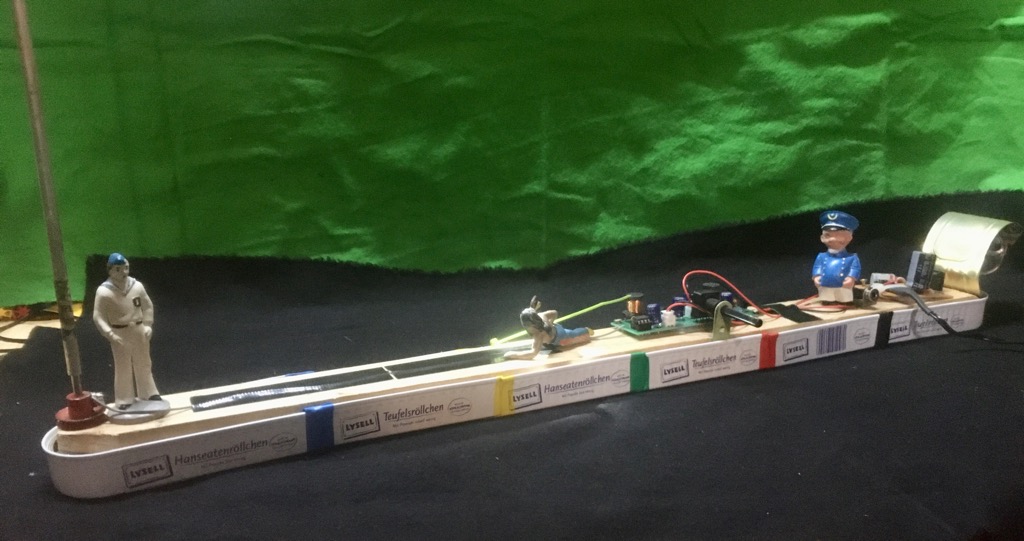
Theremin - submarin : special edition made by Karsten Bauch, Dresden
design files :
German How-To : CMOS555-Theremin_HOW2_DE.pdf
Schematics : theremin_555-SCH.pdf
assembled PCB pic : Theremin_PCB_ASY.jpg
KICAD V7.x files : 555CMOS_Theremin_KICAD.zip
respect CC NC BY SA and let me know if you publish a new version
LTSPICE LC- Schmitt-Trigger oscillator example : Theremin_HC14_CVout.asc